

How To Repair Saab 9000 Upper Engine Mount Bushing
Replacing the Saab 9000 hydraulic engine mountings
Introduction
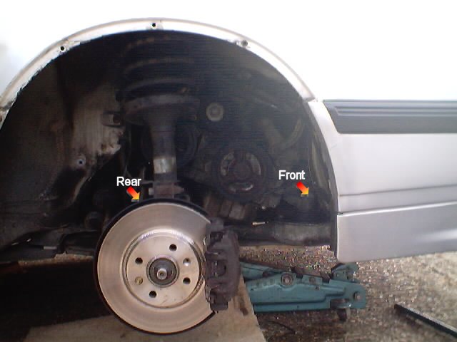
The Saab 9000's engine is mounted to the subframe on two hydraulic mountings, with a third rubber mounting under the transmission. A torque control arm connects the top of the engine to the body of the motorcar, limiting movement at the peak. While the transmission mounting seldom gives trouble, the hydraulic engine mountings accept a trend to fail, resulting in excessive move and noise, difficulty in irresolute gear, excessive vesture on the upper torque arm which somewhen results in failure of the upper torque arm bushes, and eventually, frazzle failure. These are often, but not e'er, accompanied by "clunking" sounds while moving off. My car was clunking badly, and getting rapidly worse, and I could experience the gear linkage rubbing while changing gear. Engine noise and road noise were considerable, and I assume they were being transmitted directly from the engine to the subframe past the metallic-to-metal contact immune past the failed mountings.
I gained the conviction to tackle this job from Quasi'due south spider web site, where he has published a procedure for engine mounting replacement on his 1991 9000. Yet, I plant some different ways of doing things, perhaps related to my machine being a "new shape" 9000 (1996), and and so accounted information technology useful to publish my ain account.
This procedure assumes you will be replacing both engine mountings. Since much of the piece of work involved is common to replacing both mountings and since the rear engine mounting oft fails soon after failure of the front engine mounting, it makes sense to replace both at the same fourth dimension.
Note
You may wish to consider applying the engine mounting modification documented at the Townsend Imports spider web site prior to installation. I didn't alter the mountings.
Time required
Naturally, this will vary with both the individual and what they detect when they get at that place. However, this took me nigh 2 hours. This was my first time and I imagine I could do it again in less time, barring any unforseen holdups and given the apply of a longer socket extension (see below). I won't be spending time taking notes and photographs, either (well, maybe some photographs, as I'm sure I could improve on those shown here).
Tools required
I assume some basic tools, such as a jack, beam stands, socket set, etc. However I do not assume you lot volition already accept all the necessary metric socket and spanner sizes, especially if you are in the USA. Here is a list and then you tin can make sure you have all the necessary sizes earlier you showtime.
Spanners
- 13mm
- 14mm
- 16mm
Sockets
- 8mm
- 10mm
- 13mm
- 14mm
- 16mm
- 17mm
Other
- It is desirable to have a 24" (at least) socket extension, or 2 12" extensions
Procedure
- Jack upwards the front of the car and identify it on axle stands. If you are non certain where you can safely place the jack and axle stands on a 9000, become hither for more data.
- Remove the front right-manus roadwheel.
- Remove the right front inner wing liner, documented here.
- Unscrew and remove the 16mm bolt securing the pinnacle of the front engine mounting to the engine bracket.
- Unscrew and remove the 16mm commodities securing the top of the rear engine mounting to the engine bracket. On my machine this bolt was already loose! This bolt is a little tight to get to. Y'all'll need a small ratchet (socket wrench) and a curt extension.
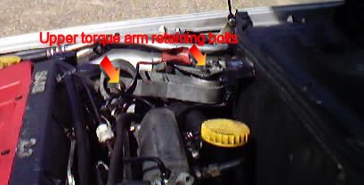
- Remove the bolts securing the upper torque control arm using a 16mm spanner and 16mm socket and remove information technology. Information technology may be necessary to remove the power steering fluid reservoir from its mounting to gain admission (mine simply slid upwards and off). On my automobile, the front bolt will not slide all the style out. However, information technology is not necessary to remove it completely, as the torque arm is slotted on ane side to clear the commodities. I have read that the front bolt comes out completely on earlier models and it is necessary to do this on these models to remove the arm.
- Raise the engine slowly by either securing an engine hoist to the lifting eyes on top of the engine, or past jacking upward the sump using a sturdy piece of wood to spread the load and avoid damage. Watch both higher up and below for annihilation that might be straining as you raise the engine and continue going as far every bit it will become without straining. I accept non used a hoist, nor know what precautions are necessary. With a jack, however, place blocks or another support underneath the engine to back up the engine in case of jack failure. I wedged a convenient concrete block nether the transmission cease of the engine. Recollect, you will probably be getting your easily between the engine and the mountings and you don't desire the engine falling at that bespeak!
- Remove the two 13mm bolts securing the front engine mounting to the subframe. While the rear commodities is piece of cake to remove, the front commodities is harder to get at. The easiest way is to use a 24" socket extension (or ii 12" extensions) and access the commodities from above the engine compartment. Since I just had a singe 12" extension, I used this to undo the front end commodities from nether the bike arch, with about 30 degrees of motility. Both bolts were a little tight due to some corrosion
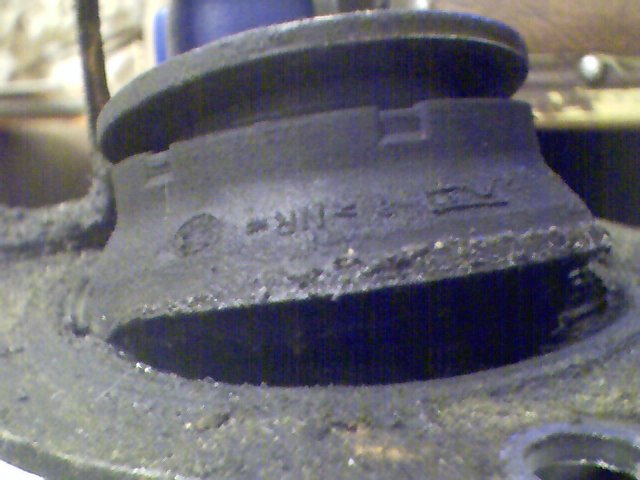
- Wriggle the front mounting out of the subframe. This is what mine looked similar (under stress). The rubber has separated.
- Wriggle the new front end mounting into the subframe and refit the bolts. I practical copper grease (anti-seize compound) to the threads to ease refitting and subsequent removal. Torque the bolts to 30Nm (22lbft).
- Using a 17mm socket underneath, a 13mm socket or spanner above for the front commodities and a 14mm socket or spanner above for the rear bolts, remove the three bolts securing the rear mounting to the subframe.
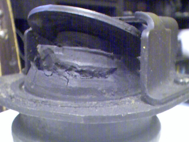
- Slide the rear mounting forrad and out of the subframe. Hither is my old rear mounting (once more under stress). Again, the failure is obvious.
- Slide the new rear mounting into the subframe and refit the bolts and basics. Torque the bolts to 30Nm (22lbft).
- Carefully lower the engine. Watch the alignment of the engine brackets on the engine mountings. I had to terminate and lightly tap the top plate on the front mounting to get information technology to locate in the engine bracket. The rear bracket settled on its mounting without intervention.
- Refit the two 16mm bolts to the top of the engine mountings. Torque the bolts to 40Nm (30lbft). The top plate of the mounting is keyed to the engine bracket to stop rotation, then there is no risk of damaging the rubber by twisting it.
- Refit the upper torque control arm and the power steering reservoir.
- Replace the inner cycle arch liner as described here.
- Refit the roadwheel.
- Lower the car.
- Torque the roadwheel bolts to 115Nm (85lbft).

Source: https://www.saab9000.com/procedures/powertrain/enginemount.php
Posted by: parkerthenteavill.blogspot.com
0 Response to "How To Repair Saab 9000 Upper Engine Mount Bushing"
Post a Comment